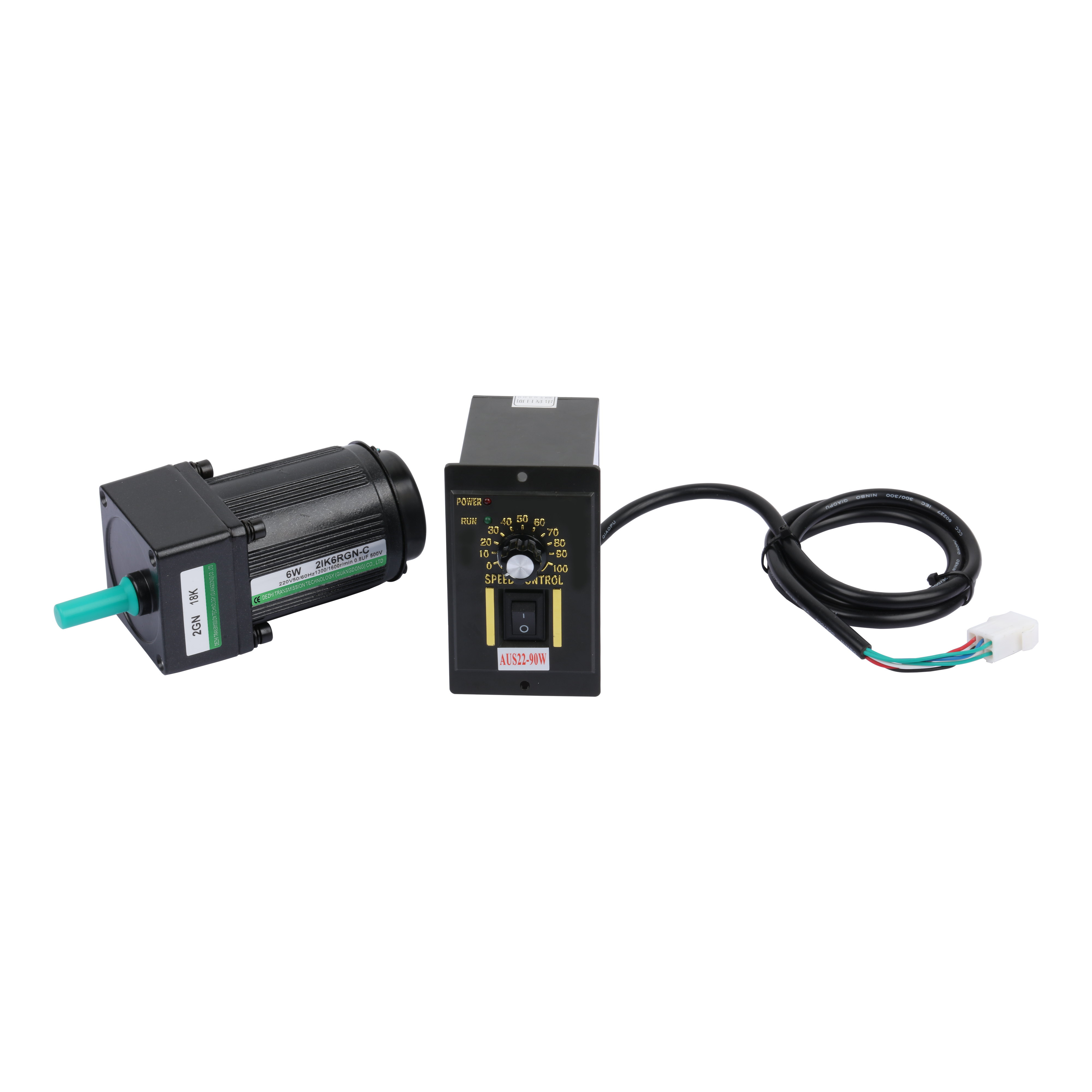
Source:Industry News Release time:2022-09-24 Clicks:0 Popular:Reduction motor manufacturer

The cycloidal pinwheel reducer is a new type of transmission system that uses the basic principle of large planetary transmission and adopts cycloid needles. All transmission systems of cycloidal pinwheel reducers can be divided into three parts: input part, reduction part and output part. There is a double stop ring with a displacement of 180° on the key shaft. The eccentric sleeve is equipped with two ball bearings called rotating arms, forming an H structure. The core holes of the two rotating wheels are stopped. The swing arm rolling bearing dovetail guide on the ferrule meshes with a set of annular pin teeth on the pin gear through the cyclone wheel, forming an internal gear reduction mechanism with a tooth difference of one tooth (in order to better reduce friction, when the transmission is relatively small In the reducer, the pin teeth contain a pin tooth sleeve).
The hard tooth surface reducer is a mechanical equipment with relatively high precision. The purpose of applying it is to reduce the speed ratio and increase torque. The applicable fast shaft speed ratio does not exceed 1500 rpm, the peripheral speed of the gear transmission system does not exceed 20m/s, and the operating temperature is -40℃-45℃.
The gears of the hard-tooth surface reducer are made of high-toughness, low-carbon, environmentally friendly carbon steel through carburizing and quenching, and the tooth surface has high hardness. Stable, low noise; small size, light weight, long service life, high load-bearing capacity; easy to maintain and install.
Hard tooth surface reducers are widely used in metallurgical industry, mining, lifting, transportation, concrete, engineering construction, chemical plants, textile industry, printing and dyeing plants, pharmaceutical industry and other industries. The hard tooth surface reducer is a driving force transmission mechanism that uses the speed regulator of the gear to reduce the number of revolutions of the motor to the required number of revolutions to obtain a relatively large torque device.
Recommended reading
Analysis of stepper motor driver
How to clean the internal parts of the right angle planetary reducer
Related Information
Small reduction motor
2020-12-21Governor
2020-12-21CGX042
2021-01-13Planetary reducer
2021-04-15Accessories
2020-12-21Planetary reducer
2021-04-15CGXZ115
2021-01-13Stepper motor
2021-04-14Planetary reducer
2021-04-15Planetary reducer
2021-04-15Stepper motor
2020-12-21Stepper motor
2020-12-21Gear reduction motor
2021-04-17Brake motor
2020-12-21Planetary reducer
2020-12-21Stepper motor
2021-04-14Planetary reducer
2021-04-15CGF-090L1-10-P2
2020-12-21