Source:Industry News Release time:2022-07-06 Clicks:0 Popular:Reduction motor manufacturer

Analysis of stepper motor driver
1. The pulse mixing circuit mixes pulse feed, manual return to origin, error compensation, etc. into positive and negative pulse feed signals;
2. The addition and subtraction pulse distribution circuit synthesizes the simultaneous positive and negative pulses into one-way feed pulses;
3. The acceleration and deceleration circuit adjusts the pulses to pulses that conform to the acceleration and deceleration characteristics of the stepper motor. The frequency changes must be stable and the acceleration and deceleration have a certain time constant;
4. The ring distributor converts the passing pulses into level signals to control the on and off of the stator winding of the stepper motor;
5. The milliamp level current output by the power amplifier ring distribution output device is used for power amplification, and is generally composed of a preamplifier and a power amplifier.
Several points that need to be paid attention to during application after stepper motor selection
The more energy invested in the early selection of a stepper motor, the less maintenance the motor will require later on. After selecting the appropriate stepper motor model, the editor will share with you several precautions that engineers should pay attention to during the application process of stepper motors.
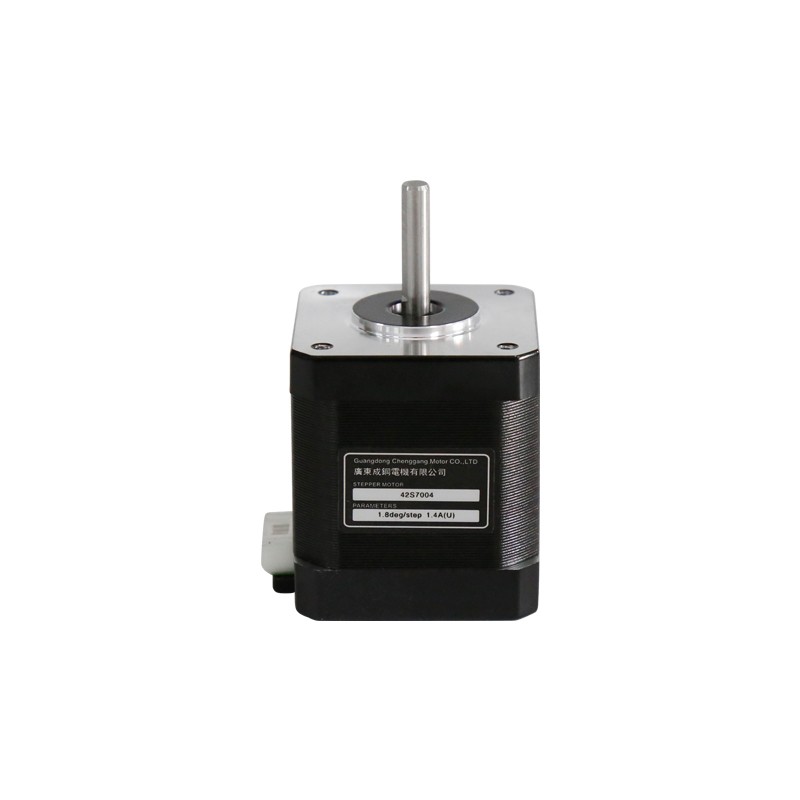
A stepper motor is an open-loop control element that converts electrical pulse signals into angular displacement or linear displacement. Under non-overload conditions, the motor's speed and stop position only depend on the frequency and number of pulses of the pulse signal and are not affected by load changes. That is, a pulse signal is added to the motor and the motor rotates by a step angle. The existence of this linear relationship, coupled with the fact that stepper motors only have periodic errors and no cumulative errors. It makes it very simple to control using stepper motors in control areas such as speed and position.
Recommended reading
Reasons for reducer seal leakage
How to use lubricating oil correctly for right angle reduction motors
Related Information
CGXK115
2021-01-13CGXZ142
2021-01-13Stepper motor
2020-12-21CGX042
2021-01-13CGXZ115
2021-01-13Planetary reducer
2021-04-15Accessories
2020-12-21CGXZK042
2021-01-13Stepper motor
2020-12-21Right angle motor
2020-12-21Planetary reducer
2021-04-15CGF-090L1-10-P2
2020-12-21Stepper motor
2021-04-14Stepper motor
2020-12-21Stepper motor
2020-12-21CGXZ060
2021-01-13Stepper motor
2020-12-21Stepper motor
2021-04-14