Source:Industry News Release time:2022-07-11 Clicks: Popular:Reduction motor manufacturer

The screw engages with the nut, and a certain method is used to prevent the relative rotation of the screw and the nut, allowing the screw to move axially. Generally speaking, there are currently two ways to achieve this transformation. The first step is to build a rotor with internal threads in the motor. The internal threads of the rotor mesh with the screw to achieve linear motion. The second is to use the screw as the output shaft of the motor, and the external transmission nut meshes with the screw outside the motor to achieve linear motion. The result is a greatly simplified design that enables precise linear motion using linear stepper motors without the need for external mechanical linkage in many applications. Linear stepper motors are widely used in manufacturing, precision calibration, precision fluid measurement, precision position movement and many other high-precision requirements.
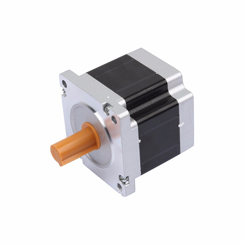
The rotor of the screw stepper motor is a permanent magnet. When current flows through the stator winding, the stator winding generates a vector magnetic field. The magnetic field will drive the rotor to rotate at an angle so that the direction of the rotor's pair of magnetic fields is consistent with the direction of the stator's magnetic field. When the vector magnetic field of the stator rotates by an angle, the rotor also rotates by an angle along with this magnetic field. Every time an electrical pulse is input, the motor rotates by an angle and moves forward one step. The angular displacement output by the screw stepper motor is proportional to the number of input pulses, and the rotational speed is proportional to the pulse frequency. Change the order in which the windings are energized and the motor will reverse direction. Therefore, the rotation of the stepper motor can be controlled by controlling the pulse number, frequency and energization sequence of each phase winding of the motor.
Common types of motors have iron cores and winding coils inside. Windings have resistance and cause losses when power is applied. Losses are proportional to the resistance and the square of the current. This is what we often call copper loss. If the current is not a standard DC or sine wave, harmonic losses will also occur; the iron core will have hysteresis. The eddy current effect also produces losses in the alternating magnetic field, the size of which is related to the material, current, frequency and voltage, and is called iron loss. Both copper and iron losses manifest themselves as heat, which affects the efficiency of the motor. Screw stepper motors generally pursue positioning accuracy and torque output. The efficiency is relatively low, the current is generally large, and the harmonic content is high. The frequency of AC current also changes with speed, more severely than with ordinary AC motors.
Use of screw stepper motor
1. When the screw stepper motor is working, each phase winding is not continuously energized, but is energized in sequence according to a certain rule.
2. Each time a pulse electrical signal is input, the angle at which the rotor rotates is called the step angle.
3. The screw stepper motor can control the angle and speed according to specific instructions. In angle control, every time a pulse is input, the stator winding switches once and the output shaft rotates by one angle. The number of steps is consistent with the number of pulses, and the angular displacement of the output shaft is proportional to the input pulses. When adjusting the speed, continuous pulses are fed into the stepper motor windings, each phase winding is continuously energized in turn, and the stepper motor rotates continuously, and its speed is proportional to the pulse frequency. Changing the energization sequence, that is, changing the rotation direction of the stator magnetic field, can control the motor to rotate forward or reverse.
4. The screw stepper motor has self-locking ability. When the control pulse stops inputting and the winding controlled by the previous pulse continues to pass direct current, the motor can remain in a fixed position, that is, stop at the end position of the angular displacement controlled by the previous pulse, so that the stepper motor can achieve rotor positioning when it stops.
Recommended reading
Basic knowledge of right angle planetary reducer
How many cooling methods are there for disc planetary reducer lubricating oil?
Related Information
CGX060
2021-01-13Stepper motor
2020-12-21Rod motor
2021-04-17Stepper motor
2021-04-14Accessories
2020-12-21Right angle motor
2020-12-21Planetary reducer
2021-04-15Planetary reducer
2021-04-15Planetary reducer
2021-04-15Planetary reducer
2021-04-15CGXZK060
2021-01-13Stepper motor
2020-12-21Stepper motor
2021-04-14Speed motor
2020-12-21CGZF-042L1-5-P2
2020-12-21Reduction motor manufacturers share the installation steps and precautions for cycloidal pinwheel re
2022-09-09Application of reduction motor
2022-08-01Reasons for reducer seal leakage
2022-12-29In what fields are stepper motors with brakes mainly used?
2022-06-29Introduction to the principles and uses of stepper motors
2022-03-10Introduction to the functions and principles of linear reduction motors
2022-11-01Analyze the difference between planetary reducer and other reducers
2022-11-28Maintenance precautions during the running-in period of the reducer
2022-12-10How to maintain the internal parts of the angle planetary reducer
2022-10-14Application advantages and characteristics of linear screw stepper motors
2022-06-06Share the brake structural features of stepper motors
2022-07-08Applicable conditions for precision planetary reducer
2022-11-14Forms and prevention of reducer gear tooth failure
2022-12-30There are several types of structures of reduction motors
2022-07-22Application of stepper motors in CNC machine tools
2022-06-09